


Please Leave Us A Message
Privacy statement: Your privacy is very important to Us. Our company promises not to disclose your personal information to any external company with out your explicit permission.

Shenzhenshi Zhenhuan Electronic Co., Ltd
 August 11, 2021
This article is mainly about the related introduction of PFC voltage-stabilized switching power supply, and focuses on the detailed description of the function and performance characteristics of PFC voltage-stabilized switching Power Supply.
PFC regulated switching power supplyPFC is the meaning of power factor correction, which is mainly used to characterize the utilization efficiency of electrical energy by electronic products. The higher the power factor, the higher the utilization efficiency of electric energy.
The PC power supply adopts traditional bridge rectifier and capacitor filter circuit, which will cause serious waveform distortion of AC input current and inject a large number of higher harmonics into the grid. Therefore, the power factor of the grid side is not high, only about 0.6, and it is not good for the grid. And other electrical equipment cause serious harmonic pollution and interference. As early as the early 1980s, people have been concerned about the harm caused by the high-order harmonic currents generated by such devices. In 1982, the International Electrotechnical Commission formulated the IEC55-2 specification for limiting high-order harmonics (the later revised specification is IEC1000-3-2), prompting many power electronics technicians to start harmonic filtering and power factor correction ( PFC) technology research. The introduction of PFC circuits into electronic power products can greatly improve the utilization efficiency of electrical energy.
There are two types of PFC, one is passive PFC (also known as passive PFC) and the other is active PFC (also known as active PFC). Passive PFC generally uses inductance compensation to reduce the phase difference between the fundamental current and voltage of the AC input to increase the power factor, but the power factor of passive PFC is not very high, only 0.7~0.8; Composed of inductance, capacitance and electronic components, it is small in size and can achieve high power factor, but the cost is higher than that of passive PFC.
Active PFC circuits often use highly integrated ICs, and PC Power Supplies that use active PFC circuits have at least the following characteristics:
1) The input voltage can be from 90V to 270V;
2) The line power factor is higher than 0.99, and it has the advantages of low loss and high reliability;
3) The PFC of the IC can also be used as an auxiliary power supply, so when using an active PFC circuit, a standby Transformer is often not needed;
4) The output does not change with the fluctuation of the input voltage, so a highly stable output voltage can be obtained;
5) The active PFC output DC voltage ripple is very small, and it is a sine wave of 100Hz/120Hz (2 times the power frequency), so the power supply using active PFC does not need to use a large-capacity filter capacitor.
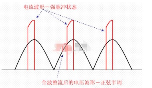
Since the 1980s, a large number of high-efficiency switching power supplies have been used in electrical appliances. Since switching power supplies use a large-capacity filter capacitor after rectification, the load characteristics of the electrical appliances are capacitive. When the AC 220V is used to supply power to the electrical appliance, the DC voltage at both ends of the filter capacitor has a slightly sawtooth ripple due to the charging and discharging effects of the filter capacitor. The minimum value of the voltage on the filter capacitor is far from zero and is not much different from its maximum value (peak ripple). According to the unidirectional conductivity of the rectifier diode, the rectifier diode will be turned on due to the forward bias only when the instantaneous value of the AC line voltage is higher than the voltage on the filter capacitor, and when the instantaneous value of the AC input voltage is lower than the voltage on the filter capacitor When the voltage is higher, the rectifier diode is cut off due to reverse bias. In other words, in each half cycle of the AC line voltage, the diode will only turn on near its peak value. Although the AC input voltage still generally maintains a sine wave waveform, the AC input current presents high-amplitude spikes, as shown in Figure 2. This severely distorted current waveform contains a large number of harmonic components, causing a serious drop in the power factor of the line.
In the positive half cycle (1800), the conduction angle of the rectifier diode is much less than 1800 or even only 300-700. Due to the requirement of ensuring the load power, a large conduction current will be generated during the extremely narrow conduction angle. , The power supply current in the power supply circuit is pulsed, which not only reduces the efficiency of power supply, but more serious is that it will produce severe AC voltage waveform distortion when the power supply line capacity is insufficient or the circuit load is large (Figure 3 ), and generate multiple harmonics, thereby interfering with the normal operation of other electrical appliances (this is electromagnetic interference-EMI and electromagnetic compatibility-EMC issues).
figure 2:
Since the inductive load of electrical appliances in the past (early televisions, radios, etc., all used inductive devices with power transformers) to capacitive loads with rectifiers and filter capacitors, the meaning of power factor compensation is not only for power supply The problem of the different phases of voltage and current is more serious to solve the electromagnetic interference (EMI) and electromagnetic compatibility (EMC) problems caused by the strong pulse state of the power supply current.
This is a new technology developed at the end of the last century (its background stems from the rapid development and wide application of switching power supplies). Its main purpose is to solve the electromagnetic interference (EMl) and electromagnetic compatibility (EMC) problems caused by the severe distortion of the current waveform caused by the capacitive load. Therefore, modern PFC technology is completely different from the past power factor compensation technology. It is adopted for non-sinusoidal current waveform distortion, forcing the AC line current to track the instantaneous change of the voltage waveform, and keeping the current and voltage in the same phase, making the system appear Pure resistive technology (line current waveform correction technology), this is PFC (power factor correction).
Therefore, modern PFC technology completes the correction of the current waveform and also solves the problem of in-phase voltage and current.
For the above reasons, the capacitive load electrical appliances that require electrical power greater than 85W (some data show greater than 75W) must add a correction circuit to correct the load characteristics to make the load characteristics close to resistive (voltage and current waveforms are in phase And the waveform is similar). This is the modern power factor correction (PFC) circuit.
Introduction to the function of switching power supply with PFCThe full English name of PFC is "Power Factor Correction", which means "power factor correction". Power factor refers to the relationship between effective power and total power consumption (apparent power), that is, effective power divided by total power consumption The ratio of the amount (apparent power). Basically, the power factor can measure the extent to which electricity is effectively utilized. The larger the power factor value, the higher the power utilization rate. The cost of switching power supply with PFC is relatively high.
The switching power supply is a capacitive input circuit, and the phase difference between its current and voltage will cause the loss of exchange power. At this time, a PFC circuit is needed to improve the power factor. There are currently two types of PFC, passive PFC (also known as passive PFC) and active PFC (also known as active PFC).
Passive PFC is generally divided into "inductance compensation" and "valley fill circuit (Valley Fill Circuit)" "inductance compensation method" is to reduce the phase difference between the fundamental current and voltage of the AC input to improve the power factor, passive PFC includes Silent passive PFC and non-silent passive PFC. The power factor of passive PFC can only reach 0.7-0.8, which is generally near the high-voltage filter capacitor.
"Valley-filling circuit type" is a new type of passive power factor correction circuit, which is characterized by using the valley-filling circuit behind the rectifier bridge to greatly increase the conduction angle of the rectifier tube. By filling the valley point, the input current is changed from the peak pulse It becomes a waveform close to a sine wave, and the power factor is increased to about 0.9, which significantly reduces the total harmonic distortion. Compared with the traditional inductive passive power factor correction circuit, its advantages are that the circuit is simple, the power factor compensation effect is significant, and the input circuit does not need to use a large inductor with a large volume and a heavy weight.
The active PFC is composed of inductors, capacitors and electronic components. It is small in size and uses a dedicated IC to adjust the current waveform to compensate for the phase difference between current and voltage. Active PFC can achieve a higher power factor ─ ─ usually up to 98% or more, but the cost is relatively high. In addition, active PFC can also be used as an auxiliary power supply, so in the use of active PFC circuits, standby transformers are often not needed, and the ripple of the active PFC output DC voltage is very small, this kind of power supply does not need to use large-capacity filtering capacitance
It is not a certain component that affects the PF. The traditionally defined phase difference is only a manifestation, and the capacitance compensation can compensate it back. This shows that it is not the inductance and capacitance that are the culprit, so it is not the problem of a certain component, but The problem is magnified, even if the "cause" is found out of nothing in a load without inductance and capacitance, it is the harmonic problem of the semiconductor rectifier diode, and then infinitely amplified, so in the end everyone does not know what PF is, in fact, there are three people. It’s just a tiger. The argument that the grid needs reactive power has been broken. 99.9% of PF power sources have been born. This basically proves that the grid operation does not require the so-called "reactive power". The cause of PF must be faced up to solve PF. So I can’t answer how you can increase the PF value. In principle, the resistance (PF=1) is used to heat and convert into electrical energy. PF is constant equal to 1. It can be seen that this is the conversion process, not the cause of the load. Of course, this conversion is actually a load, so the analysis of the problem must be realistic, and data is needed to prove it. It is not a simple reasoning. Reactive power is the definition of artificial increase in the past. The facts have not proved the mechanism and data of reactive power, but the difference between the ideal value (apparent power) and the power consumed by the load (active power). Man-made is defined as reactive power, and the power factor is generated accordingly. In fact, it is generated on the basis of man-made reactive power, which is a kind of reasoning.
The function and characteristics of PFC regulated switching power supply Among the PFC switching power supplies, the switching regulated power supply is a very important part. The difference between the switching power supply function in PFC and the ordinary switching power supply is not huge, but the power supply is different. Ordinary switching power supply requires 220V rectifier power supply, while pfc power supply is powered by B+PFC. This article will carry out a simple ![]() Introduction.
Introduction.
After rectification, no filter capacitor is added, and the unfiltered pulsating positive half-cycle voltage is used as the power supply of the chopper. Due to the series of "switching" work of the chopper, the pulsating positive voltage is "chopped" into a current waveform. The characteristics are:
1. The current waveform is discontinuous, and its envelope is the same as the voltage waveform, and the phase of the envelope and the voltage waveform is the same.
2. Due to the effect of chopping, the half-wave pulsating DC power becomes high-frequency (determined by the chopping frequency, about 100KHz) "AC" power. This high-frequency "AC" power must be rectified again before it can be stabilized by the subsequent PWM switch. Voltage source is used.
3. From the general perspective of external power supply, the power system achieves that the AC voltage and AC current are in phase and the voltage and current waveforms are in line with the sinusoidal waveform, which not only solves the problem of power factor compensation, but also solves electromagnetic compatibility (EMC) and electromagnetic interference ( EMI) problem.
The high-frequency "AC" power is rectified by a rectifier diode and filtered into a DC voltage (power supply) to supply power to the subsequent PWM switching power supply. This DC voltage is called B+PFC in some materials (TPW-4211 is the case). The B+PFC voltage output by the chopper is generally higher than the +300V after the original 220 AC rectification and filtering. The reason is that high voltage is used. The inductance has many advantages such as small wire diameter, small line voltage drop, small filter capacitor capacity, good filtering effect, and low requirements for the downstream PWM switch tube.
At present, in the PFC switching power supply part, the chopper tube (K), which plays the role of a switch, has two working modes:
1. Continuous conduction mode (CCM): The operating frequency of the switching tube is constant, and the conduction duty cycle (coefficient) changes with the amplitude of the chopping voltage.
2. Discontinuous conduction mode (DCM): The operating frequency of the chopper switch tube changes with the size of the voltage being chopped (the "on" and "off" times in each switching cycle are equal).
The PFC switching power supply part and the excitation part of the PWM switching power supply part in the power factor correction switching power supply are all completed by an integrated circuit, and a single IC can complete the design.
Concluding remarksThis is the end of the introduction to the line tube of the PFC regulated switching power supply. If there are any shortcomings, please correct me.
The above is the Introduction to the function of switching power supply with PFC Brief talk on the performance characteristics of switching power supply with PFC we have listed for you. You can submit the following form to obtain more industry information we provide for you.
You can visit our website or contact us, and we will provide the latest consultation and solutions
Send Inquiry
Most Popular
lastest New
Related Products
Send Inquiry
Privacy statement: Your privacy is very important to Us. Our company promises not to disclose your personal information to any external company with out your explicit permission.
Fill in more information so that we can get in touch with you faster
Privacy statement: Your privacy is very important to Us. Our company promises not to disclose your personal information to any external company with out your explicit permission.