


Please Leave Us A Message
Privacy statement: Your privacy is very important to Us. Our company promises not to disclose your personal information to any external company with out your explicit permission.

Shenzhenshi Zhenhuan Electronic Co., Ltd
 December 16, 2021
This article is mainly about the related introduction of the pfc circuit, and focuses on the detailed elaboration of the structure and principle of the pfc circuit.
pfc circuitThe full English name of PFC is "Power Factor Correction", which means "power factor correction". Power factor refers to the relationship between effective power and total power consumption (apparent power), that is, effective power divided by total power consumption The ratio of the amount (apparent power). Basically, the power factor can measure the extent to which electricity is effectively used. The larger the power factor value, the higher the power utilization rate. Power factor is a parameter used to measure the power efficiency of electrical equipment, and low power factor represents low power efficiency. In order to improve the power factor of electrical equipment, the technology is called power factor correction.
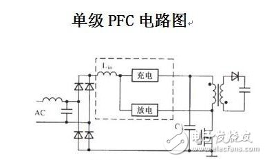
The computer switching power supply is a capacitive input circuit, and the phase difference between its current and voltage will cause the loss of exchange power. At this time, a PFC circuit is needed to improve the power factor. There are currently two types of PFC, one is passive PFC (also known as passive PFC) and active PFC (also known as active PFC).
Passive PFC
Passive PFC is generally divided into "inductance compensation" and "Valley Fill Circuit"
"Inductance compensation" is to reduce the phase difference between the fundamental current and voltage of the AC input to improve the power factor. "Inductance compensation" includes silent and non-silent. The power factor of "inductance compensation" can only reach 0.7-0.8, which is generally near the high-voltage filter capacitor.
"Valley-filling circuit type" is a new type of passive power factor correction circuit, which is characterized by using the valley-filling circuit behind the rectifier bridge to greatly increase the conduction angle of the rectifier tube. By filling the valley point, the input current is changed from the peak pulse It becomes a waveform close to a sine wave, and the power factor is increased to about 0.9, which significantly reduces the total harmonic distortion. Compared with the traditional inductive passive power factor correction circuit, its advantages are that the circuit is simple, the power factor compensation effect is significant, and the input circuit does not need to use a large inductor with a large volume and a heavy weight.
Active PFC
The active PFC is composed of inductors, capacitors and electronic components. It is small in size and uses a dedicated IC to adjust the current waveform to compensate for the phase difference between current and voltage. Active PFC can achieve a higher power factor ─ ─ usually up to 98% or more, but the cost is relatively high. In addition, active PFC can also be used as an auxiliary Power Supply, so in the use of active PFC circuits, standby transformers are often not needed, and the ripple of the active PFC output DC voltage is very small, this kind of power supply does not need to use large-capacity filtering capacitance.
Can the power supply pfc circuit be cancelledPFC means "power factor", which is mainly used to characterize the utilization efficiency of electrical energy by electronic products. The higher the power factor, the higher the utilization efficiency of electric energy. There are two types of PFC, one is passive PFC and the other is active PFC.
PFC means "power factor correction". Power factor refers to the relationship between effective power and total power consumption (apparent power), that is, the ratio of effective power divided by total power consumption (apparent power). Basically, the power factor can measure the extent to which electricity is effectively used. The larger the power factor value, the higher the power utilization rate.
Power factor is a parameter used to measure the power efficiency of electrical equipment, and low power factor represents low power efficiency. In order to improve the power factor of electrical equipment, the technology is called power factor correction.
PFC is not a new concept anymore. There are many applications in UPS power supply, while PFC circuits are rarely seen on PC Power Supplies. The rise of PFC in PC power supplies mainly stems from CCC certification. All computer power supplies that need to pass CCC certification must add PFC circuits.
PFC means "power factor", which is mainly used to characterize the utilization efficiency of electrical energy by electronic products. The higher the power factor, the higher the utilization efficiency of electric energy. The PC power supply uses traditional bridge rectification. The capacitor filter circuit will cause serious waveform distortion of the AC input current and inject a large number of higher harmonics into the grid. Therefore, the power factor on the grid side is not high, only about 0.6, and it will cause serious harmonic pollution to the grid and other electrical equipment. And interference. As early as the early 1980s, people have been concerned about the harm caused by the high-order harmonic currents generated by such devices. In 1982, the International Electrotechnical Commission formulated the IEC55-2 specification for limiting high-order harmonics (the later revised specification is IEC1000-3-2), prompting many power electronics technicians to start harmonic filtering and power factor correction ( PFC) technology research. The introduction of PFC circuits into electronic power products can greatly improve the utilization efficiency of electrical energy.
There are two types of PFC, one is passive PFC (also known as passive PFC) and the other is active PFC (also known as active PFC).
Passive PFC generally uses inductance compensation to reduce the phase difference between the fundamental current and voltage of the AC input to improve the power factor, but the power factor of passive PFC is not very high, only 0.7~0.8;
Active PFC is composed of inductors, capacitors and electronic components, and is small in size. The waveform of the current is adjusted through a dedicated IC circuit to compensate for the phase difference between the current and the voltage. The power factor of active PFC is usually more than 90%, but its cost is relatively high, so this design will only be seen in power products with higher power. 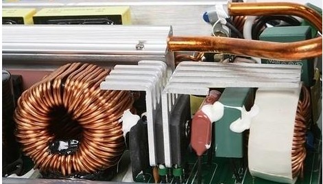
In the picture above, the coil of the PFC circuit is wrapped by white tape. From the side, we can see that the winding density of the coil is still very high. The insulating tape wound on the outside is to ensure that the coil will not affect other electronic devices when it is working.
The control and protection circuits are mostly set on the PCB of the power supply, so it is not easy to find, but some products also use a separate PCB board to make this part of the circuit. The power supply's functions such as over-current, over-voltage, over-power, under-voltage, and short-circuit protection are all accomplished by this part of the circuit.
Active PFC circuits often use highly integrated ICs, and PC power supplies that use active PFC circuits have at least the following characteristics: 1) The input voltage can be from 90V to 270V; 2) The line power factor is higher than 0.99, and has low Advantages such as loss and high reliability; 3) The PFC of the IC can also be used as an auxiliary power source, so in the use of active PFC circuits, standby transformers are often not needed; 4) The output does not change with the fluctuation of the input voltage, so a highly stable output can be obtained Voltage; 5) The DC voltage ripple of the active PFC output is very small, and it is a sine wave of 100Hz/120Hz (2 times the power frequency), so the power supply using active PFC does not need to use a large-capacity filter capacitor.
To put it plainly, the PFC circuit is to increase the +300V voltage after the bridge stack rectification to +375V----+400V. This is also the first point of the difference between the power supply of LCD TV and CRT TV. The second point of difference is that the secondary voltage is lower than that of CRT. The other parts are the same as the principle of ordinary switching power supply. The measured voltage across the large filter capacitor 330U/450V is +375V---+400V, which indicates that the power factor correction circuit is working normally; if the measured voltage across the capacitor is +300V, it means that the PFC circuit is not working, and the main check is for PFC oscillation integrated circuit.
1. What is a PFC circuit? To put it plainly, the PFC circuit is to increase the +300V voltage after the bridge stack rectification to +375V---400V. This is also the first point of the difference between the power supply of LCD TV and CRT TV. The second point of difference is that the secondary voltage is lower than that of CRT. The other parts are the same as the principle of ordinary switching power supply. The measured voltage across the large filter capacitor 330U/450V is +375V---400V, which indicates that the power factor correction circuit is working normally; if the measured voltage across the capacitor is +300V, it means that the PFC circuit is not working. Check the PFC oscillation integration Circuit.
2. When overhauling the LCD power supply; first PFC oscillator integrated circuit. First confirm the status of the fuse, the fuse is intact, usually the switch tube in the PFC correction circuit has not failed. Then measure whether there is a short circuit between the large electrolytic capacitor and the ground, and there is a charging resistance of more than tens of kiloohms, indicating that the power supply has not broken down.
3. If the fuse is damaged, the first one should check the PFC correction circuit switch tube, and the second one should check the auxiliary voltage 5 N", the general output of 40 inches below +5V, +12V, +24v three groups of voltage; 40 inches above The general output source IC. +5V, +12V, +18V, +24 V four sets of voltages. Among them, +5 V is the standby voltage, +12V is for the digital board, +18V is for the sound, and +24 V is for the backlight board. In practice During maintenance, as long as each group of power boards with the same voltage and power can be replaced.
4. The power supply board can be removed from the TV for independent maintenance. During maintenance, you only need to short-circuit the switch control circuit transistors C and E (or connect a resistance of about 1.5K to the +5V output terminal of the auxiliary power supply). The machine is in the power-on state, and each voltage has an output. In some switching power supplies for liquid crystal mining, only the +12V or +24V output terminal has a certain power load, and the main switching power supply is in normal working state. So in You can connect a 36 V light bulb of an electric bicycle to the +24V output terminal as a false load (or connect a motorcycle light bulb as a false load to the +12V output terminal).
5. After the LCD power supply is powered on, the auxiliary power supply works first and outputs +5V voltage to the CPU on the digital board. At this time, the whole machine is in the standby state. When the "standby" button is pressed, the CPU outputs the power-on level, and the PFC circuit works first, after converting the +300V pulsating DC voltage into a normal DC voltage (+380V), then the pulse width oscillator of the main switching power supply starts to work ; Then the secondary output of the main switching Transformer +12V, +24V voltage, the whole machine enters the normal working state.
6. Protection circuit. In addition to the common spike absorption protection circuit in the liquid crystal switching power supply, it is also set in +24V, +12V and +5V voltage overvoltage and overload protection circuits. The protection circuit mostly uses four operations. Amplifier LM324, quad voltage comparator LM339, dual voltage comparator LM393 or dual operational amplifier LM358. The over-current and over-voltage protection circuit can be disconnected and not used during maintenance. If the voltage returns to normal, it means that the protection circuit is caused. At this time, it is necessary to disconnect step by step which way is working. Then perform repairs.
7. Before turning on the machine, confirm whether there are any explosive parts or capacitor bulging. If so, replace and measure all related components. It is recommended that when testing the machine after replacing all the damaged components, it is best to remove the fuse of the original machine; connect a 220V/100W bulb, which can effectively prevent the parts from being blown up again.
8. The output current of the main switch voltage of +24V or +12 V is relatively large, which requires higher rectifier diodes. Generally, low-dropout high-power Schottky diodes are used, which cannot be replaced by ordinary rectifier diodes. In addition, after the load is connected, the voltage rises instead, which is mostly caused by poor power filtering.
9. The load capacity of the power supply is poor. First, check whether the PFC voltage is normal (380V). If it is normal, the problem lies in the thick film of the power supply. It is usually caused by the poor load capacity of the thick film of the power supply. Please pay attention to this point.
10. On the power board, the heat sink with the ** triangle mark and the circuit under the heat sink are all thermal grounds. Strict direct contact with your hands! Note that any testing equipment cannot be directly connected between hot and cold ground.
The above is the Can the power supply pfc circuit be cancelled? Power supply pfc circuit diagram we have listed for you. You can submit the following form to obtain more industry information we provide for you.
You can visit our website or contact us, and we will provide the latest consultation and solutions
Send Inquiry
Most Popular
lastest New
Send Inquiry
Privacy statement: Your privacy is very important to Us. Our company promises not to disclose your personal information to any external company with out your explicit permission.
Fill in more information so that we can get in touch with you faster
Privacy statement: Your privacy is very important to Us. Our company promises not to disclose your personal information to any external company with out your explicit permission.