


Please Leave Us A Message
Privacy statement: Your privacy is very important to Us. Our company promises not to disclose your personal information to any external company with out your explicit permission.

Shenzhenshi Zhenhuan Electronic Co., Ltd
 May 30, 2019
Stabilized voltage supply is an electronic device that can provide stable AC or DC power to the load, including AC regulated Power Supply and DC regulated power supply. When the grid voltage or load appears to fluctuate instantaneously, the regulated power supply compensates the voltage amplitude with a response speed of 10-30ms, which makes it stable within ±2%.
Know what is the regulated power supply, then follow the small series to understand what is the linear regulated power supply and switching power supply, then what is the difference between the two?
Comparative Analysis of Linear Regulated Power Supply and Switching Regulated Power SupplyAccording to the working state of the adjustment tube, we often divide the regulated power supply into two categories: linear regulated power supply and switching regulated power supply.
A linear regulated power supply is a regulated power supply in which the regulating tube operates in a linear state. In the switching power supply is different, the switch tube (in the switching power supply, we generally call the adjustment tube called the switch tube) is working in the open and closed state: open - the resistance is small; off - the resistance is very Big.
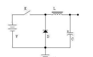
Switching power supply is a relatively new type of power supply. It has the advantages of high efficiency, light weight, high and low voltage, and high output power. However, since the circuit operates in the switching state, the noise is relatively large. Through the following figure, let's briefly talk about the working principle of the step-down switching power supply. As shown in the figure, the circuit is composed of a switch K (a triode or a field effect transistor in the actual circuit), a freewheeling diode D, a storage inductor L, and a filter capacitor C. When the switch is closed, the power supply supplies power to the load through the switch K and the inductor L, and stores part of the electrical energy in the inductor L and the capacitor C.
Due to the self-inductance of the inductor L, after the switch is turned on, the current increases relatively slowly, that is, the output cannot immediately reach the power supply voltage value. After a certain period of time, the switch is turned off. Due to the self-inductance of the inductor L (which can be compared with the image, the current in the inductor has an inertial effect), the current in the circuit will remain unchanged, that is, the flow will continue from left to right. This current flows through the load, returns from the ground, flows to the positive terminal of the freewheeling diode D, passes through the diode D, and returns to the left end of the inductor L, thereby forming a loop. The output voltage can be controlled by controlling the time the switch is closed and open (ie, PWM - Pulse Width Modulation). If the output voltage is controlled by detecting the output voltage to keep the output voltage constant, this achieves the purpose of voltage regulation.
During the closing of the switch, the inductor stores energy; during the opening of the switch, the inductor releases energy, so the inductor L is called the energy storage inductor. Diode D is responsible for providing a current path to inductor L during the off period of the switch, so diode D is called a freewheeling diode.
In the actual switching power supply, the switch K is replaced by a triode or a field effect transistor. When the switch is off, the current is small; when the switch is closed, the voltage is small, so the heating power U&TImes;I will be small. This is why the switching power supply is efficient.
After reading the two FAQs about the power supply, you may not know the power efficiency calculation. In the following FAQ, we will introduce it to you.
Common chips for switching power supplies are: TL494, LM2575, LM2673, 34063, 51414 and so on.
According to the working state of the adjustment tube, we often divide the regulated power supply into two categories: linear regulated power supply and switching regulated power supply. In addition, there is a small power supply that uses a Zener.
The linear regulated power supply mentioned here refers to the DC stabilized power supply in which the regulating tube operates in a linear state. The adjustment tube works in a linear state, which can be understood as follows: RW (see analysis below) is continuously variable, that is, linear. In the switching power supply is different, the switch tube (in the switching power supply, we generally call the adjustment tube called the switch tube) is working in the open and closed state: open - the resistance is small; off - the resistance is very Big. The tube operating in the switched state is clearly not linear.
Linear regulated Power Supplies are a class of DC regulated power supplies that were used earlier. The characteristics of the linear regulated dc power supply are: the output voltage is lower than the input voltage; the reaction speed is fast, the output ripple is small; the noise generated by the work is low; the efficiency is low (the LDO that is often seen now is to solve the efficiency problem) High heat generation (especially high-power power) indirectly adds thermal noise to the system.
Working principle: We first use the following figure to explain the principle of regulating voltage of linear regulated power supply. As shown in the figure below, the variable resistor RW and the load resistor RL form a voltage divider circuit, and the output voltage is:
Uo=Ui&TImes; RL/(RW+RL), so by adjusting the size of the RW, the output voltage can be changed. Note that in this equation, if we only look at the value change of the adjustable resistor RW, the output of Uo is not linear, but if we look at RW and RL together, it is linear. Also note that our diagram does not draw the leading end of the RW to the left and to the right. Although this is no different from the formula, but painted on the right, it just reflects the concept of "sampling" and "feedback"---the actual power supply, most of which are working in the sampling and feedback mode. In the following, there are few feedforward methods, or they are used, and they are just auxiliary methods.
Let's continue: If we use a triode or FET instead of the variable resistor in the figure, and by detecting the magnitude of the output voltage, we can control the resistance of this "varistor" and keep the output voltage constant, so we will The purpose of voltage regulation is achieved. This triode or FET is used to adjust the voltage output, so it is called the adjustment tube.
As shown in Figure 1, since the adjustment tube is connected in series between the power supply and the load, it is called a series-type regulated power supply. Correspondingly, there is a shunt regulated power supply, which is to adjust the output voltage by connecting the regulating tube in parallel with the load. The typical reference regulator TL431 is a shunt regulator. The so-called parallel means that, like the Zener tube in Figure 2, the shunting is used to ensure the "stability" of the emitter voltage of the attenuation amplifier. Perhaps this figure does not let you see that it is "parallel" at once, but Take a closer look, it is true. However, everyone should also pay attention here: the Zener here works with its non-linear region, so if it is considered a power supply, it is also a nonlinear power supply. In order to facilitate everyone's understanding, we look back at a suitable map, until we can understand it concisely.
Since the adjustment tube is equivalent to a resistor, the current will flow when the current flows through the resistor, so the adjustment tube operating in a linear state generally generates a large amount of heat, resulting in inefficiency. This is one of the main drawbacks of linear regulated power supplies. For a more detailed understanding of linear regulated power supplies, please refer to Analog Electronic Circuit Textbooks. Here we mainly help you to clarify these concepts and the relationship between them.
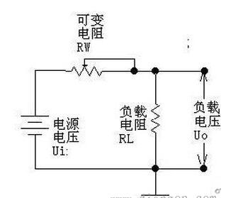
figure 1
Generally speaking, the linear regulated power supply is composed of several basic parts such as an adjustment tube, a reference voltage, a sampling circuit, and an error amplifying circuit. It may also include some parts such as protection circuits, startup circuits, and the like. The following figure is a simple schematic diagram of a linear regulated power supply (schematic diagram, omitting components such as filter capacitors). The sampling resistor samples the output voltage and compares it with the reference voltage. The comparison result is amplified by the error amplifier circuit and the control tube is controlled. The degree of conduction keeps the output voltage stable.
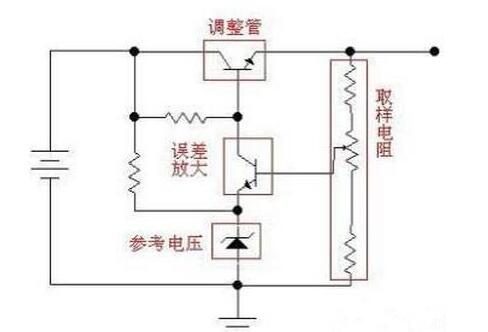
figure 2
Commonly used linear series regulator power supply chips are: 78XX series (positive voltage type), 79XX series (negative voltage type) (in actual products, XX is represented by numbers, what is XX, and what is the output voltage. For example, 7805, output voltage 5V); LM317 (adjustable positive voltage type), LM337 (adjustable negative voltage type); 1117 (low dropout type, there are many models, the voltage value is represented by the mantissa. For example, 1117-3.3 is 3.3V, 1117-ADJ It is adjustable).
1, DC to DC includes boost (buck), buck (buck), Boost / buck (l / b) and reverse phase structure, with high efficiency, high output current, low quiescent current, etc., with integration The improvement of the peripheral circuits of many new DC-DC converters only requires inductors and filter capacitors; however, the output controllers of this type of power supply have large output ripple and high noise.
2. LDO: The outstanding advantages of low dropout linear regulators are the lowest cost, lowest noise and lowest quiescent current. It also has few peripheral components, usually with only one or two bypass capacitors. The new LDO achieves the following specifications: 30μV output noise, 60dB PSRR, 6μA quiescent current, and 100mV dropout. The main reason why LDO linear regulators can achieve these characteristics is that the internal trim tube uses a P-channel FET instead of a PNP transistor in a typical linear regulator.
The P-channel FET does not need the base current drive, so the power supply current of the device itself is greatly reduced. On the other hand, in the structure using the PNP transistor, in order to prevent the PNP transistor from entering saturation and reduce the output capability, it must be guaranteed. The large input-output voltage difference; the P-channel FET voltage difference is roughly equal to the product of the output current and its on-resistance, and the small on-resistance makes the dropout very low. When the input voltage and output voltage in the system are close, LDO is the best choice for high efficiency. Therefore, LDOs are mostly used in applications that convert lithium-ion battery voltages to 3V. Although 10% of the final discharge energy of the battery is not used, LDOs still provide longer battery life in low-noise structures.
The switching regulator power supply realizes voltage conversion and voltage regulation by turning DC into a high frequency pulse and then performing electromagnetic conversion. The linear regulated power supply is directly connected in series with a controllable adjusting component to divide the input DC voltage to realize voltage conversion and voltage regulation, which is essentially equivalent to connecting a variable resistor in series.
The switching regulator power supply is highly efficient, and can be stepped down when boosted. The linear regulated power supply can only be stepped down and has low efficiency. The switching regulator power supply will generate high frequency interference, and the linear regulated power supply will have no interference. Each has its own advantages and disadvantages.

The above is the What is the difference between linear regulated power supply and switching power supply? Comparative analysis of linear regulated power supply and switching regulated power supply we have listed for you. You can submit the following form to obtain more industry information we provide for you.
You can visit our website or contact us, and we will provide the latest consultation and solutions
Send Inquiry
Most Popular
lastest New
Related Products
Send Inquiry
Privacy statement: Your privacy is very important to Us. Our company promises not to disclose your personal information to any external company with out your explicit permission.
Fill in more information so that we can get in touch with you faster
Privacy statement: Your privacy is very important to Us. Our company promises not to disclose your personal information to any external company with out your explicit permission.