


Please Leave Us A Message
Privacy statement: Your privacy is very important to Us. Our company promises not to disclose your personal information to any external company with out your explicit permission.

Shenzhenshi Zhenhuan Electronic Co., Ltd
 November 23, 2020
Power factor compensation: In the 1950s, an improved method was proposed for Power Supply inefficiencies due to the different voltage and current phases (Figure 1) of AC appliances with inductive loads (due to the current lag of inductive loads. Voltage, due to the different voltage and current phase of the power line to increase the burden on the power supply line efficiency, which requires the use of a capacitor in parallel with the inductive appliances to adjust the voltage and current phase characteristics of the appliance, such as: The 40W fluorescent lamp used at the time required a parallel 4.75μF capacitor). The capacitor is connected to the inductive load, and the characteristic of the current leading voltage on the capacitor is used to compensate for the characteristic of the current lag voltage on the inductor to make the overall characteristic close to the resistance, thereby improving the inefficiency method called power factor compensation (AC power The power factor can be represented by the cosine function value cosφ of the phase angle between the supply voltage and the load current.)
figure 1

Voltage and current waveforms in power supply lines with inductive loads
In the 1980s, a large number of high-efficiency switching power supplies were used for electrical appliances. Since the switching power supply uses a large-capacity filter capacitor after rectification, the load characteristics of the electrical appliances become capacitive. Caused the AC 220V power supply to the appliance, due to the filter capacitor charging and discharging, the DC voltage at both ends of the sawtooth wave appears slightly. The minimum value of the voltage on the filter capacitor is far from zero, and there is not much difference with its maximum value (peak ripple value). According to the unidirectional conductivity of the rectifier diode, the rectifier diode will be turned on by the forward bias only when the AC line voltage instantaneous value is higher than the voltage on the filter capacitor, and when the instantaneous value of the AC input voltage is lower than the filter capacitor At the voltage, the rectifier diode is turned off due to reverse bias. In other words, the diode will only turn on in the vicinity of its peak value during each half cycle of the AC line voltage. Although the AC input voltage remains roughly sinusoidal, the AC input current exhibits high amplitude spikes, as shown in Figure 2. This severely distorted current waveform contains a large number of harmonic components, causing a serious drop in line power factor.
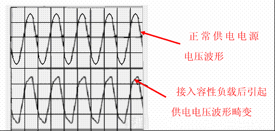
In the positive half cycle (1800), the conduction angle of the rectifier diode is much smaller than 1800 or even 300-700. Due to the requirement of ensuring the load power, an extremely large conduction current is generated during the extremely narrow conduction angle. The supply current in the power supply circuit is pulsed, which not only reduces the efficiency of the power supply, but more seriously it generates a serious waveform distortion of the AC voltage when the capacity of the power supply line is insufficient or the circuit load is large (Figure 3). ), And generate multiple harmonics, thus, interfere with the normal operation of other electrical appliances (this is electromagnetic interference - EMI and electromagnetic compatibility - EMC issues).
figure 2

Since the use of electrical appliances has changed from past inductive loads (inductive devices using power transformers for Power Supplies of earlier televisions, radios, etc.) to capacitive loads with rectifying and filtering capacitors, the meaning of power factor compensation is not only for power supply. The problem of different phases of voltage and current, more serious is to solve the electromagnetic interference (EMI) and electromagnetic compatibility (EMC) problems caused by the strong pulse state of the supply current.
This is a new technology developed at the end of the last century (its background stems from the rapid development and wide application of switching power supply). Its main purpose is to solve electromagnetic interference (EMl) and electromagnetic compatibility (EMC) problems caused by severe distortion of the current waveform caused by capacitive loads. Therefore, the modern PFC technology is completely different from the past power factor compensation technology, which is adopted for the non-sinusoidal current waveform distortion, forcing the AC line current to track the instantaneous change of the voltage waveform trace and keeping the current and voltage in phase, so that the system is presented Purely resistive technology (line current waveform correction technology), which is PFC (Power Factor Correction).
Therefore, the modern PFC technology completes the correction of the current waveform and also solves the in-phase problem of voltage and current.
image 3
For the above reasons, a capacitive load electrical appliance requiring more than 85 W of electrical power (some data shows greater than 75 W) must be corrected by adding a correction circuit that corrects its load characteristics so that its load characteristics are close to resistive (voltage and current waveforms are in phase with each other. And the waveform is similar). This is a modern power factor correction (PFC) circuit.
The above is the Power Factor Correction (PFC) Circuit Operation we have listed for you. You can submit the following form to obtain more industry information we provide for you.
You can visit our website or contact us, and we will provide the latest consultation and solutions
Send Inquiry
Most Popular
lastest New
Related Products
Send Inquiry
Privacy statement: Your privacy is very important to Us. Our company promises not to disclose your personal information to any external company with out your explicit permission.
Fill in more information so that we can get in touch with you faster
Privacy statement: Your privacy is very important to Us. Our company promises not to disclose your personal information to any external company with out your explicit permission.